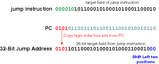
The Jump Instruction
In our schematic programs, the "jump" instruction gave a 32-bit address that goes into the PC.
How does a 32-bit instruction specify a 32-bit address? Some of the instruction's bits must be used for the op-code. Here is the assembly language version of the jump instruction.
j    target     # after a delay of one machine cycle,
                # PC  <-- address of target
Here is the machine language form of the instruction:
   6              26
000010 00000000000000000000000000    -- fields of the instructuion

opcode         target                -- meaning of the fields
There is room in the instruction for a 26-bit address. The 26-bit target address field is transformed into a 32-bit address. Here is how this is done:
Instructions always start on an address that is a multiple of four (they are word-aligned). So the low order two bits of a 32-bit instruction address are always "00". Shifting the 26-bit target left two places results in a 28-bit word-aligned address. Now the high-order four bits in the PC are concatenated to the high-order end of the 28-bit address to form a 32-bit address.
