Introduction to Magnetic Disks
Material Stolen from Dr. Kent Foster's CSCI 325 Course Notes
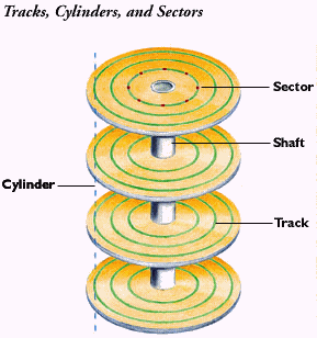
Construction
One or more disks are mounted on a spindle.
The disks are sometimes called "platters". The spindle is connected to shaft of a drive motor.
The drive motor rotates continuously at a constant speed (measured in RPM’s).
The disk material is non-magnetizeable (using aluminum and/or glass),
but the disk surfaces are coated with a very thin magnetizable coating.
 Read/write recording head (one or more) for each disk.
The R/W heads are attached to an "access arm".
The access arms are attached to a "boom".
The boom is connected to a "step" motor (also called a "servo-motor").
The step motor moves the boom and R/W heads to a
track position and stops there before a read or write operation can occur.
Read/write recording head (one or more) for each disk.
The R/W heads are attached to an "access arm".
The access arms are attached to a "boom".
The boom is connected to a "step" motor (also called a "servo-motor").
The step motor moves the boom and R/W heads to a
track position and stops there before a read or write operation can occur.
On a hard drive, the read/write heads float on a cushion of
air over the surfaces of the disks.
The smaller the air gap, the closer the read/write head is to surface,
the smaller the magnetized spot.
So, the smaller the air gap is made, the more dense the recording of
bits will be. Contaminants on the surface are larger than the air gap:
| air gap | .00003 (30 millionths of an inch)
|
| human hair | .003 (3 thousandths of an inch)
|
| paper | .003
|
| smoke particle | .0015
|
| dust particle | .0003
|
| finger prints | .0006
|
If a contaminant "crashes" into the R/W head, then as with a
car going over a large bump, the R/W head is forced up and
then the access arm will slam it down onto the recording
surface and gouge the magnetizable material off the surface,
called a head crash. This makes the disk unusable.
This was a significant problem when disk surfaces
were exposed to the ambient air which is filled with particulates.
Hence, newer drives have the disks, spindle, R/W heads,
access arms and boom enclosed in a sealed case that will
not allow contamination from the outside environment.
This technology was developed by IBM and was known as
Winchester disk technology in the past, but the term has
since been dropped since all hard disk drives now are
constructed this way.
Sectors
Each track is divided into a whole number of sectors.
Sector size is fixed for the disk.
All PC's use sectored track organization with 512 byte sectors.
Some other sector sizes that have been used by various manufacturers
are 256 and 1024 bytes.
A single disk operation = a read or write operation on one track.
The minimum amount of data transferred between the computer and the drive is 1 sector.
The max amount transferred in a single disk operation is 1 whole track of sectors.
Files are stored in a whole number of sectors. In other words, a file that needs
2.5 sectors of space consumes 3 whole sectors.
For most disk drives, all of the tracks have the same number of sectors.
Other disk drives have groups of tracks with different numbers of sectors.
If not all sectors have the same size, then inner disk tracks will have
fewer sectors than outer tracks since the inner tracks have a smaller
circumference than outer tracks.
Some hard drives to have 40+ sectors on inner tracks
and 50+ sectors on the outer tracks.
If all tracks have same number of sectors, then the linear
recording density of the outer track is less than the
inner tracks. But, the tracks hold the same amount of
data and so we will not use the linear recording density
of a track as a useful measure. Rather, we use the track
capacity measured in bytes/track (B/trk) as the track measure
(as opposed to bytes/inch for drives that have different # of sectors.)
For example, the old 1.44 MB 3.5" diskette with 18 sectors
per track and 80 tracks per surface has track capacity:
   cap = 512 bytes/sector * 18 sectors/track * 80 tracks/surface * 2 surfaces
       = 1,474,560 bytes
       = 1440 KB
       = 1.44 MB
On most disk drives, each sector begins with a small header that contains a gap and
address mark. Most manufacturers also end each sector with an error correcting code.
(For the students who have taken Networking course, think "check bits".)
Exercise #1:
    Assuming:
               File Size = 500,000 bytes
       Sectors per Track = 63
             Sector Size = 512 bytes

   Determine:
      # sectors for the file =
   min # tracks for the file =
Access Time
There are 3 delay times involved in accessing and transferring data
between the computer and the disk drive.
- Seek time delay.
- Rotational time delay.
- Transfer time delay.
It is **VERY** important to note that all these calculations are omitting the
time necessary for the CPU to transmit data along the system bus to/from the
disk drive controller.
Seek Time
The seek time for a disk operation is the time
required to move the read/write head from the current
track position to the target track position.
What causes the delay?
- The R/W head is stopped over the current track.
- The step motor must move the stopped R/W head across the surface to the target track
- The R/W head must become stationary over the target track
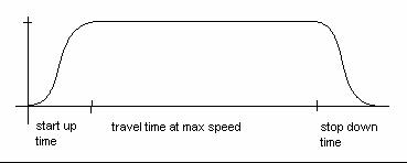 Characteristic seek time is determined by the "head movement profile"
described by the graph.
There are three time components in this movement profile:
Characteristic seek time is determined by the "head movement profile"
described by the graph.
There are three time components in this movement profile:
- start up time - the time for the R/W head to start moving from rest until it is traveling at maximum linear speed
- travel time at max speed - the time the head travels at maximum linear speed until it begins to slow down
- stop down time - the time required to bring the R/W head from its max. speed to a stationary position over the target track
For short track to track head moves, the drive never reaches max head movement speed.
Just have some start-up time and stop-down time.
Long track to track head moves are called "Full stroke seek".
For example, movement from the outer track to the inner track, or vice versa.
Startup and stop down times are a small percentage of the total full stroke seek
Travel time mainly spent passing over other tracks at maximum head movement speed.
Most manufacturers only give average read and write seek time.
For example, WD Cavier 10.1GB is 9.5 ms.
There is no way for the programmer to know how much seek time is
required because the position of the R/W head is unknown before the disk operation.
The seek time is Non-deterministic (cannot be determined absolutely).
So we must measure seek time "statistically", that is, using
statistical measures of the seek time value:
- Minimum seek time,
- Average seek time
- the "expected" seek time, denoted E(seek)
- Maximum seek time, Max(seek)
Typical values:
- Min seek is between 1 ms up to < 10 ms
- Avg seek 10 ms to 20 ms
- Max seek from < 20 ms to > 30 ms
Rotational Latency
The rotational latency for a disk operation is the time required to rotate the
disk to a position where the start of target data is under the
read/write head. The rotational latency is based on rotation speed.
Latency is non-deterministic (it cannot be determined absolutely for
any given disk operation, in general), and so must be treated "statistically",
that is, using statistical measures of the latency:
- Max latency = time of a full revolution = sec / rev
- Average latency = time of ½ revolution = ½ of max latency
Disk rotation speed is measured in Revolutions Per Minute (RPMs). To determine
rotational latency, we need to know the time for one rotation - in other words,
minutes per rotation. Hence, latency is the inverse of speed.
Time of revolution can be computed as the inverse of revolutions per time. So, time per
revolution = 1 / ( rev / time ).
For example, assume we have a 3600RPM drive,
                          1
  Max Latency =  -----------------
                      rev / time


                         1
              =  -----------------
                 3600rev / 60 secs


                      60 secs
              =  -----------------
                     3600 Rev


                      1 sec                1000ms        16.67ms
              =  -----------------   =   ----------  =  ---------
                     60 Rev                60 rev         1 rev

              = 16.67ms per revolution
So, the max latency = 16.67ms and the average latency = 8.33ms.
Transfer Time
The transfer time for a disk operation is the time
required to transfer the data from (or to) the disk surface
to (or from) the computer once the start of the data is
under the R/W head.
Transfer time is based on:
1 - speed of rotation
2 - density of data on the track
3 - amount of data to be transferred
The rotational speed of the drive and the track capacity,
or track density, can be combined into a single value
which is the transfer rate.
Remembering that one track = 1 revolution, we find ...
Transfer Rate = track capacity / rotational speed
and so, the time to transfer a set of data is
Transfer Time = Transfer Rate * Amount to Transfer
For example, the HP9154A:
   Rotation Speed = 3000RPM      --> 20ms/rev
      Sector Size = 256 Bytes
   Track Capacity = 28 sectors   --> 7KB / track

So, transfer rate = 7 KB / 20ms
                  = .35 KB / ms
                  = 3.5KB / sec
Note that the manufacturer's transfer rate will vary because of the block headers
briefly mentioned above.
Example
Let's look at the manufacturer's spec sheet for the Seagate Barracuda 7200.10 Serial ATA,
model number ST3750640AS.
| Capacity | 750 GB
|
| Discs | 4
|
| Sectors per Track | 63
|
| Bytes per Sector | 512
|
| Speed | 7200 RPM
|
| Avg Latency | 4.16 ms
|
| Track-to-Track Seek Time | <0.8 ms for read; <1.0 ms per write
|
| Average Seek, Read | < 8.5 ms
|
| Average Seek, Write | < 10.0 ms
|
Exercise #2:
1 - We computed an Average Latency for a 3600 RPM drive to be 8.33ms. So,
how can Seagate say their 7200RPM device has a 4.16ms Average Latency?
2 - How many tracks are on one each side of their platters?